Background
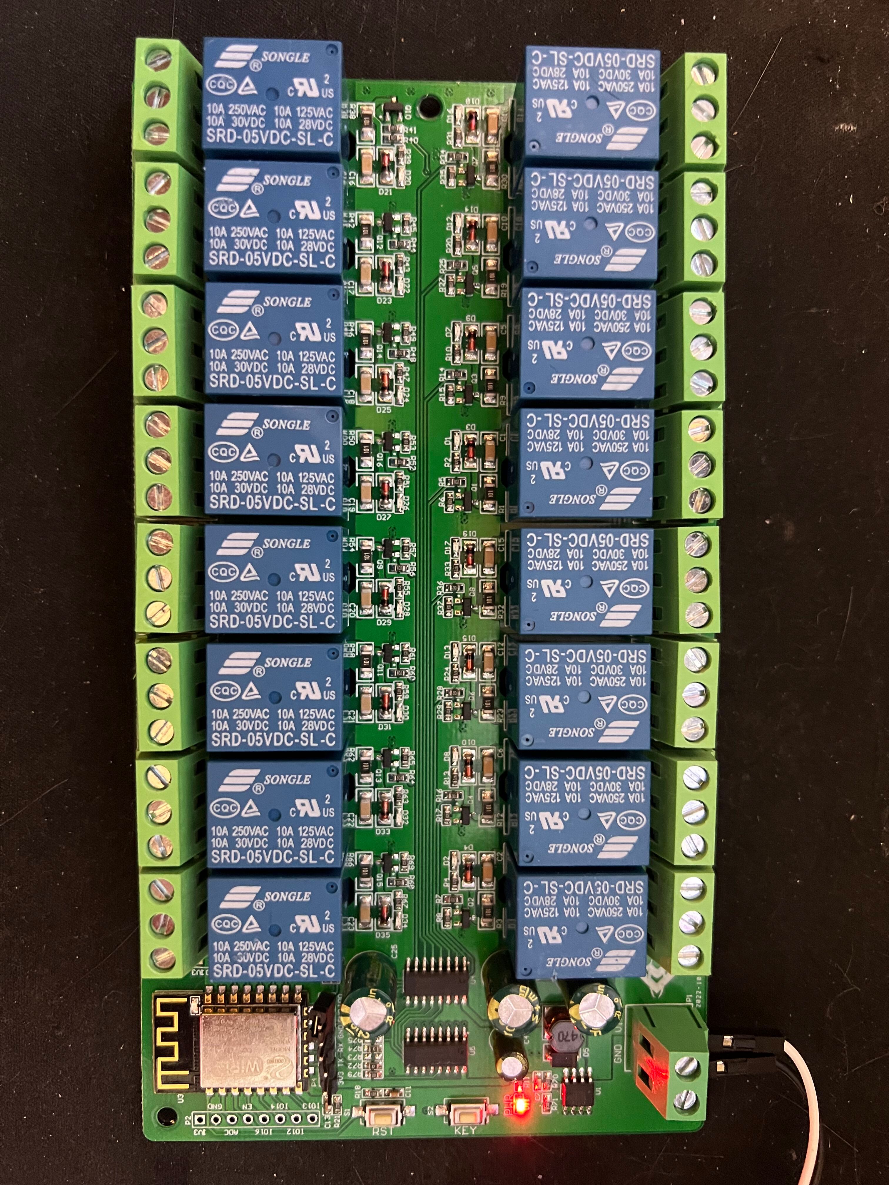
I have a number of older Amazon purchased 16 channel relay boards and decided to get an ESP32 based module with WIFI to try controlling them via ESPHome on Home Assistant. When I was looking at them I found another option: A 16-channel SPDT relay board with the controller built in.
Overview
The board works as described mostly. However during a power reset there is a flicker. Plus with the ESPHome firmware it automatically reverts to off - the relay default state. On the plus side the Home Assistant side seems to do a great job at reflecting the relay state correctly - even after reset.
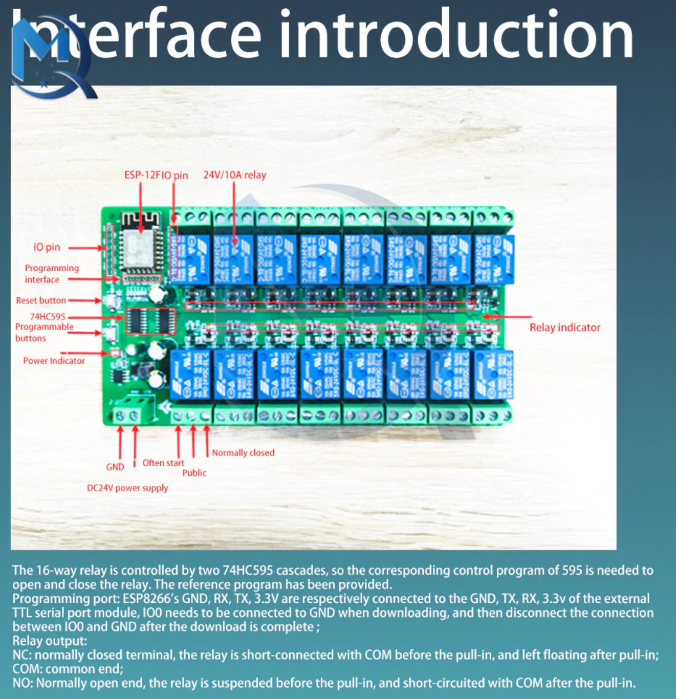
The two shift registers that control the relays can be managed via ESPHome by the sn74hc595 module. Just set the sr_count to 2 so that access to all 16, rather than the first 8 only, is available.
When the board is powered on the first time using +5VDC from a USB Serial Module it goes into an automatic program where it turns the relays on, then off, in sequence. It's really quite annoying.
It also enables an open SSID. The network used is 192.168.4.0/24 with 192.168.4.1 being the device. While the one being tested didn't respond via https, it might have had a redirect for http->https. No real investigating was made into this as ESPHome+Home Assistant was going to be the final solution.
Programing
Initial
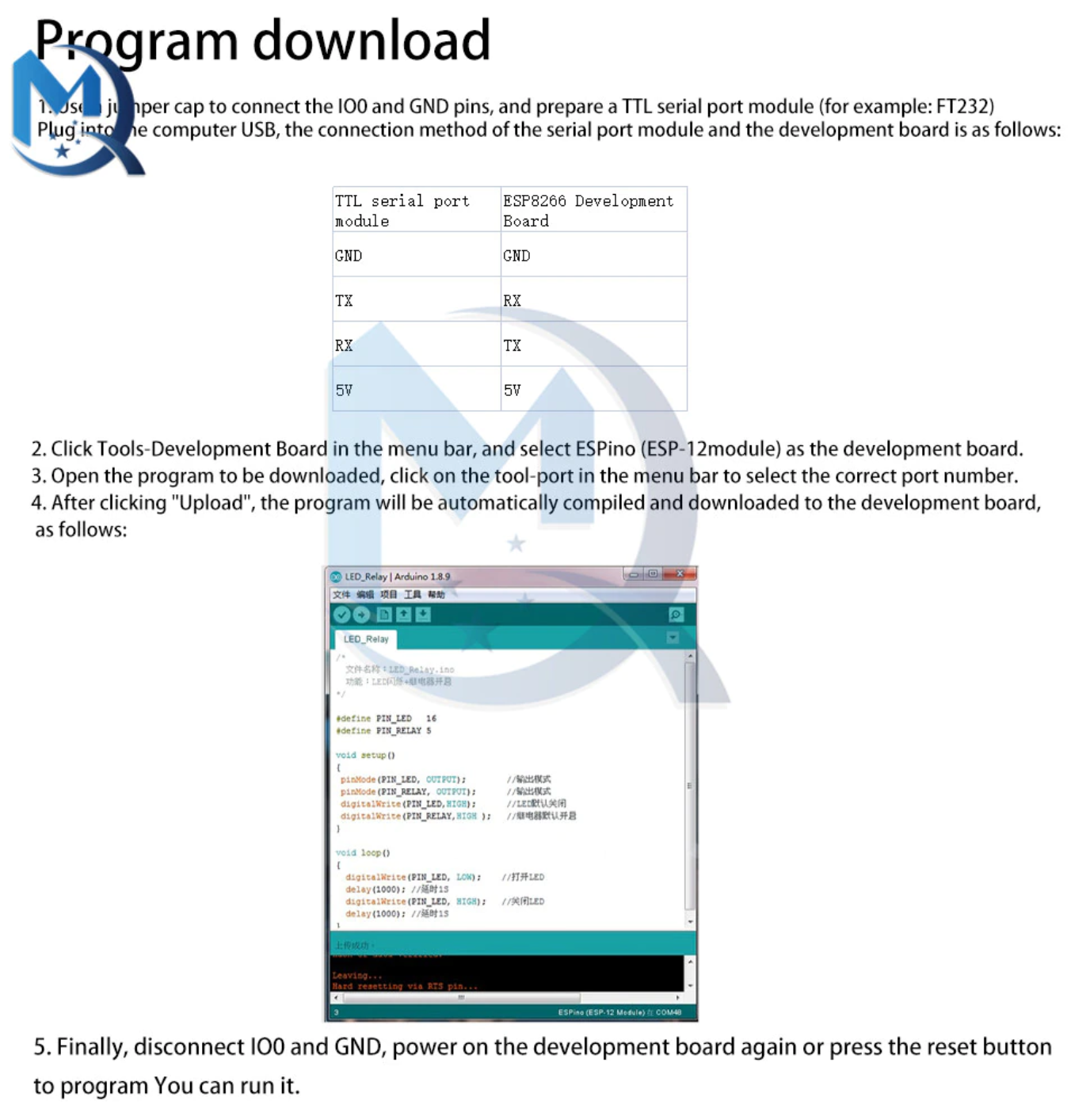
The first time programing requires using serial. I used a tiny USB Serial module with header pins to perform the initial programing and power the board during programing. Since this might need to be done multiple times during the early testing a header from the provided set was soldered on. Something like pogo pins will probably be my long term solution for initial programing of these modules.
Once the headers were in place, the IO0 and GND were connected using a provided jumper. This enables programing mode for the ESP8266 chip via serial. The 3.3v, GND, RX, and TX on the USB Serial module were connected to the 3.3v, GND, TX, and RX on the board, respectively. Note that the TX and RX are swapped. The 5v from the USB Serial module was then connected to the V+ for the board's power supply.
Once the board is powered on ESPHome can be used to add->program the board automatically. Afterwords it joined the local WIFI network that ESPHome was already programmed to use without any issue. Although a manual power cycle via the reset button (marked RST) was required post program. The jumper also must be removed before the reset.
Configuration
After the board was online in ESPHome configuration is possible by editing the device's YAML in ESPHome's web interface.
Platform And Board
First thing to do is change the platform to "esp8266" and the board to "esp12e". While the board is actually an "esp12f", there doesn't seem to be such a board in ESPHome as of 2023-04-16.
esp8266:
  board: esp12e
Shift Register
Second step is to add a "sn74hc595" block for the device's 595 chips. This ESPHome page describes this module. The pins below are correct for the module I purchased. Thanks to this reviewer for noting the correct GPIO pin constants to reference.
sn74hc595:
  - id: 'sn74hc595_hub_0'
    data_pin: GPIO14
    clock_pin: GPIO13
    latch_pin: GPIO12
    oe_pin: GPIO5
    sr_count: 2
Relay Control
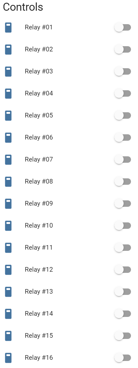
The relays themselves are controlled via switches normally. Below is an example of the YAML for the first relay off pin zero. Using a bit of Python via an interactive terminal the remaining configuration was quickly created. A full example configuration can be found here.
switch:
  - platform: gpio
    name: "Relay #01"
    pin:
      sn74hc595: sn74hc595_hub_0
      # Use pin number 0
      number: 0
      inverted: false